Machine Vision Metrology
What is Machine Vision Metrology?
Machine vision metrology is a type of metrology that uses optical imaging and machine vision techniques to measure and analyze physical objects. It involves using light sources, cameras, lasers, and other optical components to capture images of objects and then process those images to extract measurements, e.g., length, height, depth, straightness, flatness, etc. It is also referred to as optical metrology. Machine Vision Metrology is used in various industries, including manufacturing and research.
It is common in aerospace to refer to all optical surface quality control activities as machine vision inspection. This can involve measuring aircraft wing length or detecting foreign objects in the composite materials. Inspection measurement is one major part of machine vision. However, not all those activities are in the domain of metrology. It is important to differentiate the two so that you can apply the right methods to achieve the design goal.
The Difference Between Inspection Measurement and Optical Metrology
Inspection measurement uses cameras and image processing algorithms to measure physical quantities such as dimensions, shape, and position. This can include techniques such as 2D and 3D imaging, pattern recognition, and edge detection. On the other hand, optical metrology typically involves using specialized optical instruments and techniques to precisely measure physical quantities such as distance, angle, and surface characteristics.
The boundary between inspection measurement and optical metrology is not always clear-cut, as there is some overlap between the two fields. For example, inspection systems can sometimes incorporate optical metrology techniques such as interferometry or confocal microscopy for measuring surface characteristics. Similarly, optical metrology techniques can sometimes use machine vision algorithms for image processing and analysis.
In the following section, I will take the definition from ISO standards as examples. Note that there are many other standards in the domain of Metrology. We will cover the topic of selecting the right ones in another article.
Four Major Aspects of Machine Vision Metrology
Displacement and Distance. Distance measures a value between two points. It is a vector quantity. Displacement measures a change in length, and it is a scalar quantity. For example, when we measure the stringer length of a flap, it is a displacement measure. The stringer is located on a 3D base surface, and the target value is the contour of the stringer. However, the height of the stringer is the distance measurement. Correspondingly, when we use the 3D point cloud to measure the length of a scratch by calculating the absolute distance of two endpoints, we are looking for a distance value. If we use a line scan camera triggered by an encoder to measure the same scratch, it is not a distance value anymore. In most use cases, the difference between the two is negligible. However, in high safety-critical applications, it is recommended to define the requirement clearly.
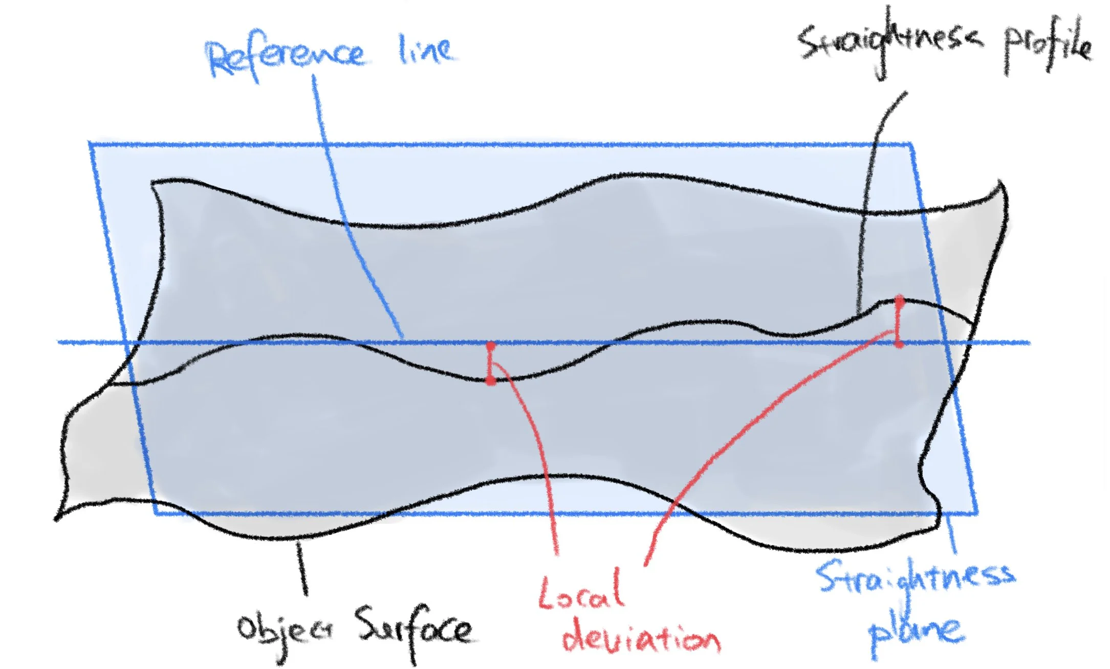
Straightness and Alignment. ISO 12780-1 defined straightness as the total deviation of the straightness profile to the reference line. In practice, the major challenge is defining the Straightness Plane and finding the Reference Line. In aircraft inspection, it is common to use design data (technical drawings or CAD models) to extract the references.
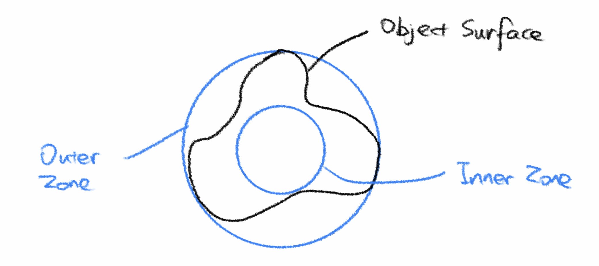
Flatness, Roundness, Sphericity, Cylindericity. All refer to 3D surface properties. They are typically measured by the minimum zone method. The Minimum Zone Method involves finding the smallest zone that completely encloses a set of data points, such that the feature or surface lies entirely within the tolerance zone. This zone is defined by two parallel planes offset from the feature or surface by the maximum and minimum distance to the data points. The distance between these two planes is the tolerance zone for the feature.
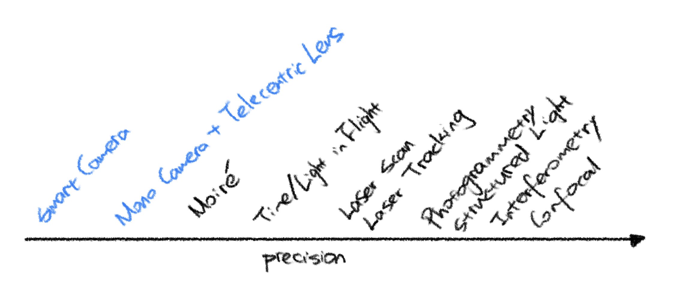
Surface Profilometry and 3D Shape Measurement. This refers to measuring the three-dimensional shape of an object. 3D shape measurements are used to accurately measure the dimensions of complex objects, including curved and irregular shapes. It involves capturing a 3D point cloud or surface mesh of the object using techniques such as structured light scanning, laser scanning, or photogrammetry.
In the aerospace industry, 3D shape measurement often is the base of inspection. Acquiring the 3D shape of any subcomponent of aircraft or even the full aircraft poses several challenges. How to cover the object's entire surface with a strict spatial resolution requirement? How to select and position the sensors to obtain the best data quality on non-monolithic surface finish/material? How to stitch the data from multiple sensors/sensor paths highly accurately? All the above questions need to be answered. They are the essential building blocks of a Large-Scale Machine Vision (LSMV) system. Solving such complex problems requires systematic approaches, courage, and imagination. Traditional inspection approaches, which are static and small-scale, will miserably fail to meet the goal.
Reference
Handbook of Optical Metrology: Principles and Applications, 2nd Edition. Toru Yoshizawa. 2015
ISO/TS12780-1,2003, Geometrical Product Specifications(GPS)—Straightness.Part 1:Terms, definitions, and parameters of straightness.


